


Look now at the Preferences panel (File ➤ Preferences), shown in Figure 1-2. I always use verbose output when
I’m looking for errors in the compile process. The verbose-output feature has been moved to the Preferences panel,
whereas before it could be triggered by pressing Shift plus the Compile button. The Preferences panel nowenables you to resize the compile output for easier reading.
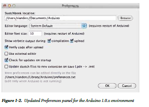
The location of the preferences.txt file is listed in the Preferences dialog box. It is good to know this because
you may need to edit this file.
Changes to Sketches
Whenever you write an Arduino sketch, you are using the core functions and collection of objects that are always
accessible, without needing to include external libraries in your sketch. For instance, Serial can be used without
having to declare it. The Arduino IDE preprocesses the Arduino sketch before compiling. This process includes the
Arduino.h file from core. Some of the files from core have to be included manually, as the Ethernet core does.
The Ethernet core features are needed for the Arduino Ethernet board, but because not all Arduino boards have
Ethernet, the files are available but not automatically included.
Arduino achieves its simplicity by preprocessing the sketch and automatically generating a basic functional set.
So, you never have to worry about including Arduino.h and creating header files for sketches, unless you create your
own Arduino libraries. Arduino libraries have to be written in standard C/C++; I will cover their creation later,
in Chapter 14.
Here, you will examine how the default core functionality has changed. Then the chapter will cover how these
changes have affected the default libraries that come with Arduino.
These default libraries have been replaced by new variants with new features. Also, WProgram.h has been change
to Arduino.h.
API Updates
This section will discuss the changes to the API.
pinMode
pinMode has been updated to support INPUT_PULLUP. This adds clean support for creating buttons and switches that
are active high by default, and when activated pulled low. Listing 1-1 shows an example.
Listing 1-1. pinMode INPUT_PULLUP Resistor Feature
setup()
{
Serial.begin(9600);
pinMode(10, INPUT);
digitalWrite(10, HIGH);
int val = digitalRead(10);
Serial.print(val);
}
In Arduino 1.0.x you can do it this way:
setup()
{
Serial.begin(9600);
pinMode(10, INPUT_PULLUP);
int val = digitalRead(10);
Serial.print(val);
)
Chapter 1 ■ Arduino 1.0.4 Core Changes
4
This approach has the benefit of making the pinMode set the default value as needed. Also, using the internal
pull-up resistors removes the need to use external pull-up resistors, allowing you to remove parts from your project.
Return Types
Return types have been updated to return the size of data using size_t, which is an unsigned integer that is platform
dependent. size_t is included from stdio.h in the Print.h header. This returns a size type for the data printed.
You can use this to check the quantity of data returned for iterating. When writing your own libraries that print custom
data, you would use size_t as the return value.
uint_8
Several functions now take and return uint_8, which is a universal 8-bit integer that allows for cross-platform
compatibility.
Arduino API Core 1.0.4
Now let’s look at the changes in the Arduino API Core.
Arduino.h
If you are using standard AVR GCC system libraries or writing your own library, it’s important to know the Arduino
library. Arduino.h now includes all the values from wiring.h. If you are already programming with C/C++, it’s good to
know which functions are already available, so that you don’t include the libraries twice.
Arduino.h includes the libraries shown in Listing 1-2, so you don’t need to include them in your own sketches.
Listing 1-2. New Headers Automatically Included in Arduino.h
#include <stdlib.h>
#include <string.h>
#include <math.h>
#include <avr/pgmspace.h>
#include <avr/io.h>
#include <avr/interrupt.h>
#include "binary.h"
#include "WCharacter.h"
#include "WString.h"
#include "HardwareSerial.h"
#include "pins_arduino.h"
You never have to duplicate the libraries in your own sketches. They are automatically included for your use.
The preprocessing compiles Arduino.h, and then combines the sketch with a file called main.cpp. This file
contains the implementation for void setup() and void loop(). In fact, it’s short enough to show in Listing 1-3.
Listing 1-3. The New Version of main.cpp
#include <Arduino.h>
int main(void)
{
init();
#if defined(USBCON)
USBDevice.attach();
#endif
setup();
for (;;) {
loop();
if (serialEventRun) serialEventRun();
}
return 0;
}
Looking at the source, there are two interesting items to note. First, main.cpp now looks to see if a USB
connection is defined and attached. Second, the void loop() code runs, and then a serial event is checked for.
If the event is found, then the code runs it.
Updated Serial Object
Sending data from serial is now asynchronous. The serial object depends on a parent object called stream, so it is
included automatically with HardwareSerial.h in your main sketch.
Updated Stream Class
The Stream class has been updated. This is part of the serial object and provides the search, find, and parse value
functions that the HardwareSerial object uses.
Constructor
The constructor simply sets the timeout for the serial port to a default of 1000 ms.
Stream() {_timeout=1000;}
Member Functions
The member functions are shown in Table 1-1.

The Print class has been updated. This affects the Client and Stream classes directly. The classes that include
them are affected as well. The HardwareSerial and UDP classes use Stream. Therefore, you do not specifically have
to include Print in your main Arduino sketch. Table 1-2 shows some of the more important updates to the publi cmethods.


New Printable Class
A new Printable class was created to define how new objects would be printed. Listing 1-4 shows an example.
Listing 1-4. Example of Writing Bytes
void setup()
{
Serial.begin(9600);
}
void loop()
{
byte bb = B101101;
int bytesSent = Serial.print("byte: println: ");
Serial.print(bytesSent);
Serial.print(" : ");
Serial.print(bb);
Serial.print(" write: ");
Serial.write(bb);
Serial.print("");
Serial.write(45); // send a byte with the value 45
Serial.println("");
bytesSent = Serial.write("A");
}
Updated String Library
Storing strings into flash for printing has been made easier by the F() command. Whatever string is placed between
quotation marks will be stored in flash, and will reduce the amount of RAM used.
Serial.println(F("store in Flash"));
Wire Library Updates
The Wire library also uses Stream, so it has the same features as Serial. The function Wire.send() has been replaced
by Wire.write(). Wire.receive() has changed to Wire.read().
HardwareSerial Updates
HardwareSerial now supports USB by default.
• Serial.begin() supports unsigned long declaration.
• Serial.write() now returns size_t.
• Serial.SerialEvent() has changed.
• Serial.SerialEventRun() is implemented to check for up to four defined serial ports
(Serial, Serial1, Serial2, and Serial3) and look for available serial data on each.
Physical Board Updates and USB Compatibility
All the new Arduino boards come with 16u2 chips for USB or have USB support built in, as is the case with the
Arduino Leonardo 32u4. The core now includes USB serial, keyboard, and joystick. The Arduino Leonardo has the
advantage that the USB libraries are accessible in your Arduino sketch, and you can use the new USB libraries to
program Arduino Leonardo behaviors. However, the 16u2 chips do not use the same library, and since they are
separate chips, they have to be programmed separately. Currently, the most widely developed USB support libraries
are from Paul Stoffregen for the Teensy and Teensy++ boards.
Avrdude Update
Avrdude is the uploader that Arduino uses to load program images onto the Arduino boards. The version of Avrdude
that comes with Arduino has been updated to 5.11, which supports the arduino upload type. This used to be the
stk500 upload type. All the official boards are now programmable by this arduino upload type from the 5.11 version.
Additionally, custom bootloaders and firmware can be loaded onto Arduino using Avrdude.
You can use this feature to program microcontrollers with the Arduino bootloader, so that they can run Arduino
sketches. Programmable microcontrollers include ATtiny85, ATtiny45, chipKIT Uno32, chipKIT Fubarino SD, and
user-created and designed Arduino-compatible microcontrollers.
The New Arduino Leonardo Board
Arduino revision 3 boards are already configured and updated. The variant types are defined, and the upload types
are configured for “Arduino.”
The Arduino Leonardo is based on the Atmel ATmega32u4 chip. The Leonardo board has the following features:
• MCU ATmega32u4
• Operating voltage: 5V
• Recommended input voltage range: 7–12V
• Twenty digital pins
• Seven pulse-width modulation (PWM) pins
Chapter 1 ■ Arduino 1.0.4 Core Changes
10
• Twelve analog input channels
• Flash memory: 32 KB (but 4 KB is used for the bootloader)
• SRAM: 2.5 KB
• EEPROM: 1 KB
• Clock speed: 16 MHz
A unique feature of the Leonardo is that serial data is normally handled and programmed over USB, but
the Leonardo also has pins 0 and 1, which are configured as additional serial pins. These can be used for serial
communication, in addition to USB. For instance, you can program and communicate using serial over USB, while a
device like a GPS shield can use the onboard serial pins as hardware serial, without the need to use SoftwareSerial.
Avoid the conflict generated between SoftwareSerial and the Servo library when they are used at the same time.
The firmware updates allow for the programming of the devices over USB serial. They implement an improved
reset feature that allows for a software reset, triggered by the Arduino uploader at programming time. If the Arduino is
emulating a keyboard, joystick, or mouse, you need to be able to reset the device so you can reprogram it.
In the new system SPI, however, pins are not broken out into digital pins, and are only available in the 6-pin ICSP
header. For example, the Adafruit 32u4 breakout board and the Pro Mini from SparkFun Electronics both use the
ATmega32u4 chip, and can be configured to act like an Arduino Leonardo. However, the physical pin mappings might
be different, and this is where using a variants file is really helpful.
There are also two sets of I2C pins, but they are connected to the same pins on the ATMEga32u4 chip. They do
not have internal pull-up resistors. You will have to confirm whether your shield has onboard pull-up resistors, and
if not, you will have to add them. For instance, the Adafruit RFID shield will require that external pull-up resistors be
added to the board.
Figure 1-3 is a chart stowing how the pins of the ATmega32u4 chip are mapped to the pins on the Arduino Leonardo.


In order to add the Leonard board to the Arduino IDE, they needed to define the boards.txt file, which contains
the complete definition of the board. The boards.txt file includes the board name, platform, and upload protocol.
Most importantly, the boards.txt file indicates the location of the bootloader file and the variants file to be used.
If you make your own board based on this chip, these are the critical files to update. The SparkFun Pro Mini, the
Adafruit ATmega32u4 board, and the paper Leonardo are all defined similarly; however, the Leonardo header and the
name field need to be changed in the boards.txt file to match each board (see Listing 1-5). If there were a different pin
configuration on your custom board, you would need to create your own build.variant file.
Listing 1-5. boards.txt Definition for the Arduino Leonardo
leonardo.name=Arduino Leonardo
leonardo.platform=avr
leonardo.upload.protocol=arduino
leonardo.upload.maximum_size=28672
leonardo.upload.speed=1200
leonardo.bootloader.low_fuses=0xde
leonardo.bootloader.high_fuses=0xd8
leonardo.bootloader.extended_fuses=0xcb
leonardo.bootloader.path=diskloader
leonardo.bootloader.file=DiskLoader-Leonardo.hex
leonardo.bootloader.unlock_bits=0x3F
leonardo.bootloader.lock_bits=0x2F
leonardo.build.mcu=atmega32u4
leonardo.build.f_cpu=16000000L
leonardo.build.core=arduino
leonardo.build.variant=leonardo
Board Variants
Board variants allow the defining of custom pin mappings for new and custom boards. Originally, all of these features
were maintained in a pins_arduino.h file in the core. Now the pin maps have been moved into their own folder,called variants
Variants Files
The Arduino Leonardo is a good example. The Teensy from Paul Stoffregen and the ATmega32u4 breakout board
from Adafruit both contain the same chip as the Leonardo, but have different form factors. The number of pins and
locations don’t match, so creating a board variants file helps map the pins to the common locations more easily. Like
pin 13 used for blink. Pin 7 maps to an LED on the ATmega32u4 breakout board. Adding a variant file causes those
mappings to be the same. The variants file makes it much easier to create a custom board that is Arduino compatible.
These variants files are placed into a folder named after the board or the pin layout. Then, inside boards.txt,
the variants entry needs to be added to:
boardname.build.variant=myboardpins
The files can be placed either into the application hardware/arduino/variants folder or in sketches/hardware/
myat32u4/variants.
Arduino comes with several predefined variants that support the existing Arduino boards, but this chapter will
examine the section specific to the Leonardo variants. Among the other variant folders (mega, micro, standard), there
is a new one called Leonardo. That folder contains pins_arduino.h. This is used at compile time as a reference for the
pin mappings and board-specific features.
Variant Types and Naming
The Arduino Leonardo has 12 analog inputs, but only 5 are mapped on the silk screen. However, all 12 are defined
in the variants file. This means you can use the features—even though they are not labeled—by reading the variants.
The SPI pins are not labeled, but can be accessed via the ICSP header. Here is the section where these capabilities are
defined:
I2C is defined as pins 2 and 3 on the ATmega32u4 chip, as shown in Listing 1-6.
Listing 1-6. Variant File i2C Mappings
static const uint8_t SDA = 2;
static const uint8_t SCL = 3;
SPI is defined as pins 17, 16, 14, and 15 on the ICSP header, as shown in Listing 1-7.
Listing 1-7. SPI Pin Mappings
// Map SPI port to 'new' pins D14..D17
static const uint8_t SS = 17;
static const uint8_t MOSI = 16;
static const uint8_t MISO = 14;
static const uint8_t SCK = 15;
The analog pins are defined and mapped on the ATmega32u4 to the pins shown in Listing 1-8.
Listing 1-8. Analog Pin Mappings
// Mapping of analog pins as digital I/O
// A6-A11 share with digital pins
static const uint8_t A0 = 18;
static const uint8_t A1 = 19;
static const uint8_t A2 = 20;
static const uint8_t A3 = 21;
static const uint8_t A4 = 22;
static const uint8_t A5 = 23;
static const uint8_t A6 = 24; // D4
static const uint8_t A7 = 25; // D6
static const uint8_t A8 = 26; // D8
static const uint8_t A9 = 27; // D9
static const uint8_t A10 = 28; // D10
static const uint8_t A11 = 29; // D12
The rest of the file configures the ports and other features to support these constants.
Uploader Options Renamed to Programmers
There are several programmers supported in the list. The supported programmers are
• AVR ISP
• AVRISP mkII
• USBtinyISP
• USBasp
• Parallel programmer
• Arduino as ISP
These options make it easier to program devices that don’t have serial or USB serial ports. The smaller chips, like
the ATtiny 4313, 2313, 85, and 45, can only be programmed via one of these programmers. These programmers can
also be used to put new bootloaders onto Arduino boards. Additionally, they set the chip configuration and speed.
New Bootloaders
A bootloader is the software on the Arduino board that loads the sketch into memory. The sketch is compiled into
a HEX file. The bootloader receives the HEX file from a programmer called Avrdude, and then loads it as the active
program on the device. Several new bootloaders come with Arduino 1.0.4:
• Optiboot: The bootloader for the Arduino Uno rv3.
• Diskloader: The bootloader for the Leonardo and 32u4-based boards.
• Stk500v2: The bootloader for the Arduino Mega 2560.
USB Firmware for 16u2
The firmware is for the USB support and VID information for official Arduino boards. The USB firmware for 16u2
also contains the LUFA library, which Arduino licensed for official USB support. This firmware is burnable into the
Atmega16u2, the Atmega8u2 for the Arduino Uno, and the Arduino Mega 2560. These are now updated for all the
revision 3 boards. Revision 3 also removes the FTDI USB support and replaces it with the Atmega16u2.
You need to use the DFU programmer to program this firmware into those chips. The DFU programmer is
available here: http://dfu-programmer.sourceforge.net/.
Additionally, a modification to board needs to be enabled to allow the programmer to communicate with the chip.
To enable programming via the DFU, you need to populate the second ICSP programmer, and in some cases
perform a hardware modification described here in order to start working with the 16u2.
This ultimately allows for Arduino to have an onboard USB device separate from the main microcontroller.
You will have to work out the communication protocol between the two devices. However, this will add USB device
support to the latest family of Arduino boards. I think the Arduino Leonardo offers the best of both worlds, because
instead of requiring you to program it separately, it allows you to program it using the Arduino USB API.
Summary
The Arduino 1.0.4 core changes update the built-in command structure for Arduino significantly. The changes to the
object hierarchy affect the behavior of the objects that inherit from the parent objects, allowing for a more regular and
cleaner API to program. A lot of work has also gone into supporting more boards, and updated boards, from Arduino.
The changes to the bootloaders, particularly the addition of board variants, is a significant step toward supporting
more Arduino variations. Now, your own Arduino-compatible board is much easier to create and distribute. For
example, you can use an Atemga32u4 chip on your own custom board, or even make a Leonardo-derived board like
the SparkFun Pro Mini, Adafruit Flora, or Adafruit 32u4 breakout board.
Chapter 2
Arduino Development and
Social Coding;
Improve the world through sharing your code. Participating in a community of coders brings professionalism to yourhobby. The Arduino world is a community that values the free flow of knowledge and recognizes the benefit of the
community to problem solving.
While sharing code might seem to be an unsolvable puzzle at first, many tools have been used to accomplish the
task of code collaboration. In this chapter, you will learn to use the online code-sharing community called GitHub.
Along the way, this chapter will also explore how the Arduino open source community uses modern social-coding
practices to contribute to projects.
Social coding is the idea that any code you create begins with and contributes to the work of a community of
coders and active users who want to assist you as well as to improve their own projects.
Arduino is a fast-changing platform, and its development and best practices are set not by industry standards
alone, but also by the emergent interaction between industry makers and an open source community of software
and hardware hackers. How you participate in the open source community demonstrates how you are a professional.
In the field of Arduino and open hardware, pro means using emergent techniques in social-coding communities,
alongside making and testing in open, entrepreneurial communities. Open hardware, like open source software, even
if created by a single person, is used and lives on in communities of use. So contribute your Arduino IDE source code
for the good of the world and move along.
Because Arduino is open source, it is always under revision by its community of developers. Your code can
undergo quite a bit change when starting a project, and when people begin to work collaboratively with you. The fast
pace of change in a project needs to be matched by fast updates to the documentation. You and your collaborators
will all need to have the same shared idea, and learn to describe that shared concept via documentation in a
collaborative wiki environment. Even if you work alone, documenting your process will enable you to quickly return
to projects once set aside, keep track of multiple projects at a time, or publish the software to run a kit you want to sell.
To document your project, you need to know how to create pages, and edit a project Wiki using the Markdown syntax.
This will be covered in the Documentation section of this chapter.
Components of Social Coding and Project Management
Project description, issue management, code version control, and documentation are the main components of social
coding and project management. We will dig into each one, including a description of what each is and how you
manage it through GitHub. Instead of these features all being hosted in different systems, they can all be found on
GitHub. Centralizing these features in one place helps your community of users and developers keep up to date with
the project and automatically watch for changes. The project repositories you host at GitHub can be created as public
or private repositories. You choose whether you are hosting a private project for a small team, or a public open source
project. On GitHub, you can host as many public open source repositories as you like, but you have to pay for the ability to have a private project
The first example in this chapter will be a Hello World GitHub example that you can use as a template for
structuring typical projects. All the examples for the book will be organized in a GitHub project repository:
http://github.com/proard. As we learn the tool, you will be able to not only get your own copy of the code for the
book, but you will be able to submit your changes back to the main project.
What Is a Project and How Is It Organized?
A project is the story of what you are working on, and then the hardware and code that make your physical project
blink, move, or communicate. You can’t put physical electronics on your site, so you have to put the description of the
electronics. For our purposes, these files will count as code. and how is it defined?
The basic unit of a project is the code repository. This is where the code lives. Every project is required to have a
name and a description. A readme file is strongly encouraged as well, as it is commonly used as a quick starting point
for people to pick up key concepts and examples of your project. When you use a social-coding tool like GitHub, it
derives a starter page for the project and generates the project’s own unique URL, so users of the project can find it
the project page easily. Hosting a project so that it is public and findable is a good start, but you want to encourage
even more usage and participation. When someone watches, stars, or joins a project, GitHub tracks the changes in the
repository. These changes are then emailed to them, or listed as part of their main page in GitHub.
There are two common patterns for project directory layouts. If you are creating a plain Arduino sketch, then the
folder and the sketch name are the same. So, a sketch called HelloGithub.ino would be placed in a directory called HelloGithub. As seen in Figure 2-1 for HelloGithub.
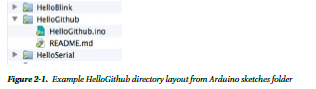
That directory would be the repository name. This way, when the project is cloned or downloaded from GitHub,
it unpacks as a valid sketch and then can be easily placed in your Arduino sketches folder as in Figure 2-1.
The second pattern is for hosting Arduino libraries you create. In Chapter 13 we go over the details for writing
libraries. In this case there is a pattern to create a repository for the Arduino library you are writing. If you were to write
a library called “HelloLibrary” you would call your repository HelloLibrary. The repository name would automatically be
the directory name that the holds the typical files in an Arduino library. However, the name of the project and the directory
should not include a “_” because Arduino doesn’t allow that in a library name. That way you do not have to change file
names when you want to download or clone the library into the Arduino sketches libraries folder, like in Figure 2-2.

The Hello Library directory layout contains the required header file, implementation file, and the common sub
directories for examples, documentation, and utility code.
Once the code is in GitHub it can be accessed in several ways from your GitHub project page. Figure 2-3, the
GitHub menu bar, shows that you can download a zip file of the project. “Clone in Mac” triggers the GitHub GUI tool
to clone or copy the project to your local computer. This option is also available for Windows and Linux.
Figure 2-3. GitHub access repository options
Figure 2-3 also shows you can also do a manual copy or clone of the project via secure Hypertext Transport
Protocol (HTTPS), or secure shell (SSH). When you use these secure protocols GitHub will allow you to not just read
data from the project, but write your changes back to the project securely. Finally, each of these techniques will allow
for your sketches to be in your Arduino sketch folder or in you Arduino sketch libraries folder, where you can use or
edit your project code.
In Arduino 1.0.5, there is now a new “Add Library” feature used to install your zipped library projects. This feature
allows you to download the zip archive version of the project directly from GitHub, and it will extract, then install, the
project into your user sketches libraries folder for you. This is very convenient for those developing Arduino libraries.
Many projects use GitHub for project and code management. There are many projects organized in this fashion.
The Arduino project and examples in this chapter are using the same principles.
• Arduino (http://github.com/arduino/arduino): The Arduino IDE source code.
• ProArduino TiltSpirit (http://github.com/proard/tiltspirit): A simple Arduino game with
LCD and tilt sensors.
• ProArduino HelloGithub (http://github.com/proard/HelloGithub): The example Hello
World GitHub for Pro Arduino.
From these project repositories you can find out the source code status, the current issues, and documentation
wiki for a project. Each example represents a project that you can use or help with.
Overview of Version Control
In the code repository is the source code for the project. This code will change depending on project progress,
features, and issues. A project that is alive changes and is revised regularly. Version control provides a method for
multiple people to use, and edit the code simultaneously, and allows you to track the beginning and growth of a
project over time. The basic unit of change in version control is the commit, which contains the list of all modified
files, plus the code changes inside of them. In our case, version control can be thought of as a list of changes that are
committed to the project by yourself or by other collaborators.
Overview of Issue Tracking
Issues are the features, bugs, and change requests for a project. A new project has goals and requirements. These are
translated into issues for which the code delivers the functionally. Tracking issues can be quite difficult. For small
projects that are about tiny tasks, a programmer can simply remember what needs to be done, but when a project
takes you a couple days or more, your community starts giving you feedback and people start wanting to help you.
In these cases, issue-tracking becomes critical. When you track issues, you keep a written list of new features and
improvements. This public list is critical, in that users of your software can add feature requests or describe a problem
in detail. A way to handle this is to assign a unique number, description, and category to each issue; this number
can then be tracked from when a new issue is reported to when the issue is closed. Even more importantly, the code
changes related to the issue need to be collected together. Every code commit should have a message describing the
collection of changes. This way there is accountability for who made the changes and when the changes were made,
and you will have a good chance of figuring out why the changes were made the way they were. In order to ensure
that the code and issue are hyperlinked together, many users write something like, “This was fixed by #issue_number.”
The good news with GitHub is that every code commit can be connected to the issue it resolves.
When working with issues it is typical to take the following steps.
1. Look for the issue in the issue list.
2. If it does not exist, file a new issue, including a concise subject, a description that includes
a way to reproduce the problem, and, if possible, a source code example or test that fails
due to the noted issue. Then the issue number is generated.
3. People watching and maintaining the project will get an automatic e-mail when you
generate your issue. If you need to discuss the issue, you can send an e-mail to the develop
list with the issue number and a hyperlink to the issue.
4. Someone may claim an issue, or you can assign it to a programmer, and that connection
between issue and programmer can be seen in the issue list. If not claimed, you can
update the code yourself to address the issue, and then create an official request that your
code fix be added to the main project. This request is officially called a “pull request.”
5. Once the issue is confirmed fixed, the issue can be marked “closed” using either the
commit, pull request, or issue manager interface.
6. If for some reason the issue is not truly resolved, you can reopen it.
This pattern helps everyone coordinate their work strategies, and divide up the effort of fixing project issues as
well as project feature goals.
Documentation
Project documentation is the identity of your wiki project. It is where code experts, and people who are not source
code experts and only want to use the project, go to find out what your project is about. It is like a Wikipedia
entry for your project. In fact, the type of documentation we will be looking at is wiki documentation. We will use
GitHub’s wiki documentation to provide a statement of purpose; a description of assembly; a link to step-by-step
images of the project; and a link to the schematics, Eagle, or Fritzing files to the printed circuit boards. Sometimes
people check only the wiki documentation and never see the source.
The GitHub wiki uses what is called Markdown formatting in order to display the text of the pages. The details
of Markdown syntax are found at https://help.github.com/articles/github-flavored-markdown. These pages
can be edited online in the wiki interface. Additionally, other people can use the wiki and help you keep information
about your project up to date.
Project Management for Social Coding
In this section, I describe one way to set up your development environment using the version control system Git and
the online code-sharing repository GitHub. Git is the distributed version control software that GitHub uses as a basis
for their social code management website.
Version Control with Git and GitHub
This section will provide one way to set up your development environment using Git and GitHub. It will drill into the
details of how to perform project management in a social-coding world. GitHub at its core is the code repository that
allows for version control.
Version control, or revision control, tracks every change made to software, including who made the change and
when it occurred. This allows for multiple people to work on software simultaneously and merge the changes into the
master code base. The tool at the heart of this is Git.
What Is Git?
Git is a powerful version control system that is used with many open source projects, including Linux Kernel, which
has thousands of contributors and projects. Among the projects tracked with Git are Arduino software projects and
projects from Adafruit Industries. The Git tool, which is a version control system that is completely distributed, allows
for a massive amount of code hacking by multiple developers across the world. Everyone with a copy of the repository
has a complete copy of the entire project with its entire revision control history. What is really unique with this is that
developers are encouraged to fork the project and make their own changes to it.
Each copy of the software is either a clone or a fork. A clone is a copy of the master online repository on
http://github.com/proard/hellogithub; you will use a clone of your project locally on your computer. A fork is an
online official copy of the repository, one that you maintain on your own GitHub account, at http://github.com/
youraccount/hellogithub. Git allows for a highly trackable and secure communication process between repositories.
You can send cryptographically signed changes between you local repository and your remote repository. This
supports secure development and accountability for who, where, when, and what changed.
Here, I will cover the basic starting commands and the preferred development process supported by the Arduino
community. GitHub provides a nice starting guide at http://help.github.com, as well. The steps presented here will
be similar to those from the guide, but they will be geared toward starting your own Arduino projects.
Installing Git
First, you must install Git locally and create an account on GitHub. Check out the “Get Started” section on GitHub,
at https://help.github.com/articles/set-up-git. The command-line version of Git can be obtained from
http://gitscm.org/ and should be installed as you would any software. I recommend selecting the shell options
for Windows. The Git shell makes it easy to access Git on the command line. There is also a GitHub GUI tool for
managing Git repositories which is helpful, but not a replacement for all of the features that come with the Git
command line software.
One additional feature of Git is that it is cryptographically signed, and every commit and change clearly trackable,
and makes programmers accountable for the changes they make. You will need to configure a unique key for your
system. To get started, you’ll need to do the following:
1. Install Git.
2. Create GitHub account at http://github.com.
3. Generate a key pair to authorize your commits.
• Mac OS X: Go to https://help.github.com/articles/generating-ssh-keys#platform-mac
• Linux: Go to https://help.github.com/articles/generating-ssh-keys#platform-linux
• Windows: Go to https://help.github.com/articles/generating-ssh-keys#platform-windows
4. Set your user and e-mail in Git at http://help.github.com/git-email-settings.
Here is the command-line option for setting your global user information:
$ git config --global user.name "Your Name"
$ git config --global user.email you@example.com
With these settings in place, your system is ready to start working with the Git repositories, and GitHub. Your
system will now properly indicate the code changes you make, and the changes you submit will be cryptographically
accountable. This makes working with GitHub seemless.
GitHub Tools
Now that you have Git installed, and a GitHub account, you have your own area for repositories and account
management on GitHub. I prefer to install the Git command line software prior to the GitHub GUI tools. That way,
there is a command-line tool and GUI access for your project files. This lets you experience the best of both worlds.
Figure 2-4 shows the GitHub GUI configured to display projects on the local system. This shows your repositories
and what organizations they belong to, as well as their overall status. It is possible to drill down into each project and
examine individual files. Importantly, the Git GUI will generate the security keys for you.

Figure 2-4. GitHub GUI on Mac OS X
You are now up and running with GitHub. GitHub GUI will list your repositories on GitHub and synchronize
changes from both your local repositories and your GitHub repositories. It provides a nice level of convenience, but
learning the command line version of Git will offer better access to the revision control features, and showing the code
differences between versions.
Version Control, Basic Workflow
In this section we introduce a basic work process for version control. This starts with creating your own example
project in GitHub, then expands to working with projects other people have created, and then reviews the necessary
Git commands that allow you to manage a version controlled project. This includes finding out what changed, and
moving your code from your local repository to your remote repository on GitHub. It is possible to have more than one
remote repository, but for this chapter your repository on GitHub will be the remote repository we use.
Creating Your Own Project
Go to GitHub and select “New repository.” Call the repository HelloGithub. Then fill in the new repository
information, as shown in Figure 2-5. Once finished, select “Create repository.”

You want to indicate that this is an Arduino project. All Arduino projects are by default C++ projects. Select the
.gitignore option for C++. This automatically keeps Git from tracking temp files and extraneous files common to C++
and text editors. Once you have selected “create repository,” you are presented with the default view of the project.
the interface should look like Figure 2-6. This view shows you the source code for your project, and links to the many features of GitHub

An initial Readme.md file is created, but you will have to manually edit the Readme.md file with a description of
your project, and how you would like people to configure the hardware, and modify the code to support different
configuration for usage. This edit can be done after you clone your repository to your local machine, or can be done by
live editing the file directly on GitHub. GitHub has a feature where you can browse your source code online and select
a file for editing. When you save a change it will be saved as a standard code commit. Just click on the file “README.
md” in Figure 2-6 to try it.
From Figure 2-6 you can clone the project locally. By cloning the project, you are in fact downloading the
repository from GitHub using the “git clone” command. This is your copy of the entire repository on your local
computer. Cloning can be done with the GitHub GUI application or on the command line, as follows:
$ git clone git@github.com:username/HelloGithub.git
In this case the “username” is your username on GitHub, and the command will copy all the files and version
control information to your local machine. This is your local repository; all changes stay in the local cloned repository
until you push your changes back to your original online repository on GitHub. “Origin” is the official name for your
repository on GitHub. Your local code changes do not automatically move to the “origin.” You will have to “push” your
change to your origin. Also, changes that you edit online directly to your GitHub project or if new code is merged into
your GitHub project from other code contributors. Those changes have to be “pulled” to your local repository.
Editing Code and Checking for Changes
Once you now have a complete copy, or local clone, of your project, the process of working with and modifying code
begins. Through the work process you will manage the changes to the project, and eventually send those changes
back to your remote repository at GitHub. You will need to know how to check to your project for changes, commit
those changes, and send them back to you GitHub repository. Then you will want to be able to get new changes form
your GitHub repository and add them to your local repository.
Code can be changed in many ways:
User git clone git@github.com:username/HelloGithub.git
Work process
Make changes to code:
• Use the Arduino IDE to edit a sketch like HelloGithub.ino.
• Add or delete files.
• Move files to various places in the project.
• Edit files in libraries with your favorite text editor.
View changes
When you do make changes, you will want to know how to review them. Any time a change is saved, you can issue the
following commands to check your work:
$ git diff
Or show a summary of changes with:
$ git diff --stat
Saving and committing changes
Once you are ready to commit to the changes you made, you can now commit these changes to your local code
repository. Only staged changes are committed without the “-a”, to commit all changes, use “-a”, like so:
$ git commit –a –m "Changed the files and fixed issue #1"
To commit only certain changed files list the named files, use the following:
$ git commit HelloGithub.ino "Update HelloGithub.ino and changed blink rate for issue #1"
Each of these commits are are identified by SHA-1 hash that represents all the changes in the commit. These
commits are saved code transferred from one repositoy or another. Also, you can check out different commits and
recreate the exact file structure and changes in their code. “HEAD” is an alias for the latest commit you have made.
The indicator “~1” is the equivalent of “-1”; they can be combined to read “HEAD~1”. It’s also possible to say “HEAD~2”
which is two commits back from HEAD. For instance, if you want to check out the previous commit you could issue the following command:
$git checkout HEAD~1
Once that checkout succeeds, the code and files match that exact commit. If you look at the file system, you will
see your old files and old changes, but all will precisely match the first commit back form “HEAD”. The syntax “HEAD”
and “^” can be used with the diff command as well. To return to your latest status, issue the command:
$git checkout HEAD
Now your files and code match the official version.
One extremely useful use case is to check out just one file. You may have make changes you are not happy with,
and you will want to only grab an early version or the current version of file. You can use:
$git checkout – filename
This immediately checks out the previous version of the file. You can checkout the file from two versions ago by
using “HEAD~2”
$git checkout HEAD~2 filename
If the file didn’t exists two version back it will complain file is not part of the commit.
You can also checkout what is called a branch:
$git branch HelloBranch
This command automatically creates a branch called “HelloBranch”, but does not switch to it.
$git checkout HelloBranch
This command will check out that branch. If you want to return to your “master” branch you can use:
$git checkout master
At some point you will want to know what branches you have. The command is:
$git branch
The result will list all the branches in your repository.
In our examples we don’t cover branching, but you should learn about branching as you use GitHub. A branch
allows you to test out new ideas, create different versions of your project, or fix code without making changes in your
master branch. In this chapter, I only cover making changes to your “master” branch.
Move changes to your GitHub repository
Now that the changes are committed to the local repository, you need to push them to your GitHub repository, which
you can do by using the following command:
$ git push
If you are working on multiple machines, or multiple people are working with you, then your project on GitHub
could have changed. You may have even accepted a “pull request”. In this case, you will want to bring those changes,
or collection of commits, to your local repository. One method is to “fetch” the changes from GitHub. This grabs the
changes as a set, but does not merge them into your code automatically. The command would be as follows:
$ git fetch
At this point, you have all the changes from the GitHub repository. You do not have to fetch until something
changes on Github again. At this point you can use “git diff” and examine the changes that were made on the
server from a local copy. Once you are ready, merge the changes from fetch into your local repository. This is the
merge command:
$ git merge master
The “master” key term is for the master branch of the code that was fetched. Most changes can be merged
without a conflict. The pull command combines the fetch of changes with a merge. This is a very convenient way to
get changes from your GitHub repository. The full command is:
$ git pull
Once you have successfully pulled your changes to from your GitHub repository. You can immediately begin
editing, changing code, and working on your project. As needed, use the above commands to help you complete these
common tasks. The options I have outlined are just for getting started with Git; it is a very complex and powerful tool.
This chapter should get you started, but for more detail on the commands, see the Apress book called Pro Git, which
can help you dig in deeper.
Workflow Summary: Creating Your Own Project
We walked through the creation of the HelloGitHub project to demonstrate GitHub’s commands, but there is a
pattern in the steps we took. Follow these same steps for any project you create and you have workflow that ensures
version control for one or multiple creators. Summarizing the steps we already took, we see the common steps for
working on any project:
1. Create the project on GitHub.
2. Clone the project to your local machine.
3. Make changes to the code.
4. Add or remove files.
5. Commit changes to your local Git repository.
6. Push those locally committed changes to your “origin” repository on GitHub.
7. Repeat steps 2–6 as needed.
These steps allow you to work locally and keep up to date with your project. You can use git diff, and git diff –stat
or any of the many Git commands to check the difference in code version, and the changes over time for the project.
Workflow Summary: Forking Another Project
Frequently there are existing projects that you want to use, but you might want to change the configuration for your
hardware, or want to add a feature to the project. Since I work with many different kinds of Arduino compatible
boards, not every project is designed to work with one I’m using. For instance, between the Arduino Uno, and the
Arduino Mega, the SPI pins are numbered differently. I will typically fork the project, and then make the needed
changes to my forked copy of the project. Once I’m sure the code changes are working, I can do a pull request that
allows the maintainer of the main project to merge those fixes to their project.
We will use the HelloGithub project at the Pro Arduino GitHub site, https://github.com/ProArd/HelloGithub,
and run through the fork process with it. Once you find the HelloGithub project, you can select fork. This copies the
project into your own GitHub area. Then you will want to make a copy to your local machine by cloning it
These are the steps for forking another project:
1. Log into http://github.com.
2. Visit http://github.com/proard/HelloFork. You will find an example of what you’ll find

3. Select the “Fork” option, in the list of buttons highlighted by Figure 2-8.

4. GitHub will tell you it is forking the project, with the processing sceen in Figure 2-9.

$ git clone git@github.com:YourUsername/HelloFork.git
7. Set the official HelloFork repository as the upstream repository:
$ cd HelloFork
$ git remote add upstream git@github.com:proard/HelloFork.git
8. Since you just cloned it there are no changes, but once changes have been made you will
want to fetch and merge changes from upstream with these commands:
$ git fetch upstream
$ git merge upstream/master
9. You can do a test of the merge by doing a dry run, using the following commands:
$ git merge --no-commit --no-ff upstream/master
$ git diff upstream/master –stat
If you want to see the difference between the changes that are being made, you can compare your code with the
code on your GitHub repository with the “diff” command:
$ git diff origin/master
You can get a quick summary of the file changes by using “—stat”
$ git diff origin/master --stat
Given this list, we need to define a couple of new concepts. First, an upstream repository is typically the project
that you forked into your GitHub repository. Secondly, every so often you will want to go back to the original project
and pick up new files and code changes, so that you can synchronize your work with the main project. Your original
project on GitHub is called “origin.” The latest version of code is called “master.” So you can compare the latest
versions of “origin/master,” or “upstream/master,” with your local repository. Over time, projects can get further out of
sync. If you fetch the changes from the upstream repository, you can bring the changes to your local machine without
clobbering your own code, without breaking existing work by hitting it with a write over. The upstream master code
will not automatically update your working area in the local master. After a fetch, you have to take specific action to
merge those changes into your own project. git merge defaults to merging the fetched master with your local working
master repository. The merge process will combine those changes into your local project.
Creating a Pull Request
In the section we will modify the HelloFork.ino sketch to have your Arduino username and submit the change as a
pull request to the official Pro Arduino repository for the HelloFork project. At this point you will already have the
forked from Pro Arduino, and cloned to your local system. So now edit the HelloFork.ino sketch to include your
GitHub username. The code will look like:
/*
* Hello Fork Github Example Arduino Sketch
* Just add your GitHUb account ID and I'll add your pull request to the project.
void setup() {
Serial.begin(9600);
}
void loop() {
Serial.println("Add your GitHub name to the code to test creating a pull request");
Serial.println("Hello Github from:");
Serial.println("@Ricklon");
Serial.println("@ProArd");
Serial.println(“@YourGitHubUsername”);
}
Once you save this code you can check the repository for the change by issuing the command:
$ git status
Result:
# On branch master
# Changes not staged for commit:
# (use "git add <file>…" to update what will be committed)
# (use "git checkout -- <file>…" to discard changes in working directory)
#
# modified: HelloFork.ino
The status result shows that you modified HelloFork.ino. This change needs to be committed to your local
repository with the following command:
git commit -m "Added a new username to the HelloFork.ino sketch." HelloFork.ino
Result:
[master f6367cf] Added a new username to the HelloFork.ino sketch.
1 file changed, 1 insertion(+)
The commit uses the “-m” to specify the message. After the message can be a list of files, paths, and or wildcards
to specify the file names and directories to include in the commit. If you want to commit all changed, added, and
deleted files, you can use the “-a” flag. This flag stands for “all.” The message can contain the Markdown shortcuts we
described in the documentation section, like @username to mention a user and link to their account. Now that the file
is committed, it is time to push the commit to your GitHub repository. That can be done be issue the command:
$ git push
Result:
Counting objects: 5, done.
Delta compression using up to 4 threads.
Compressing objects: 100% (3/3), done.
Writing objects: 100% (3/3), 408 bytes, done.
Total 3 (delta 1), reused 0 (delta 0)
To git@github.com:ricklon/HelloFork.git
4e28d3f..f6367cf master -> master
The push result summarizes all the changes and commit information that is sent to you GitHub repository. The
“To” section. The “4e28d3f..f6367cf” in the result is shorthand for the hash that represents the commit being pushed
to your GitHub repository.
Take a look at the HelloFork menu, as in Figure 2-11. Clicking on the file views the file. In our case we want to look
at the commit and see what was changed as shown in Figure 2-12.

The “+” indicates the new line of code you added. A minus, “-“ represents the removal of code.
Now your project is up to date; all changes between your local repository and your GitHub repository are now
synchronized.
Creating a Pull Request
Once all the changes you want to make are bundled in your repository it’s time to create a “pull request” that will
move your changes to the project you forked your project from. In this case we are using your HelloFork repository.
Go to the your GitHub project for HelloFork. It should appear similar to Figure 2-13.

The summary shown on Figure 2-13 shows your username, what project is selected, and where the project is
from. At the same level are the project options. We are about to use the “pull request” option. You can also “Watch,”
“Star,” or “Fork” the project from this menu. With “Fork” it shows you the number of forks of the project. If anyone
wants to make a fork of your project, they can select “Fork.” For now just select pull request button, as in Figure 2-14.
After the pull request is selected, you are shown the “pull request” management screen as shown in Figure 2-15.
Here you can decide the details of the pull request. In our case, we’re just going to ask to pull the latest changes from
our project in the master branch, to the Pro Arduino master branch.

is descriptive enough, but there are times when you need to explain more about what you are doing, and what issues
it addresses, then you can put that information in the main message area. The message area accepts Markdown, as we
described in the documentation section of this chapter. Now that you’ve got your message entered, select the “Send

The summary of this pull request identifies who made the request, and identifies the commit that you are
being asked to merge into your project. GitHub does a quick check to see if the new code can be added to the
original automatically. In our case, the merge request can be automatic. Figure 2-18 shows a close up of that portion of the screen.

In this example, the maintainer selects to “merge pull request” and then is presented with confirmation and the
opportunity to add a note about the merge as shown in Figure 2-19.

Once that merge is confirmed, then a summary screen is show as in Figure 2-20. The entire merge discussion is
listed, so that you can review the comments. You can also review the commit status before and after the merge.
If there is information about the merge that needs changing, it is possible to edit information about the merge from
this screen.

how much changed, by saying, in this case 1 commit was merged. There are times where multiple commits can bemerged at once.
Figure 2-20 also shows that the merge is “closed”; this merge was identified as “#2” in the issue system. If you
select “#2” you will be sent to the issue system, where you can see that the issue was closed as in Figure 2-21.
Since the HelloFork project currently has two issues, both pull requests that were completed are shown.
These pull request are in the Pro Arduino project that accepted your request. In Figure 2-22 the screen from
GitHub shows that two closed issues exist, and 0 open issues exist. If you made a pull request earlier to the
project, then you would see them as one or more open issues. Since pull requests are integrated into the issue
system, it is easy to find out who fixed issues, what issues were resolved, and where the changes came from. This
leads us directly to issue management.


Issue management with Github
For a quick way to think about issue tracking you can follow the following process:
1. Look for the issue in the issue list as shown in Figure 2-23.
2. If it does not exist, file a new issue and include a concise subject, a description that
includes a way to reproduce the problem, and, if possible, a source code example or test
that fails due to the noted issue. GitHub automatically e-mails the creation of new issues to
maintainers.
3. Make your modification to the project files to fix the issue and submit a pull request from
GitHub.
4. Confirm the issue is fixed by testing it.
5. Lastly, close the issue in the issue system, which will update its status.
Connecting Version Control with Issue Management
The ways you change your code and files to address an issue are collected in the message portion of a commit. These
commits represent progress towards adding features or resolving issues. Connecting this progress to the issue tracking
system is critical because you want to know what the code changes are for and you want to make it easy to track
what code fixed which issue. GitHub has added some automatic linking features that automate part of this process.
If you refer to issues by “#” pound issue number like “#1” in the commit message, or the issue comment GitHub
will automatically link to the corresponding issue number. Every code commit should have the issue number and
description of the code changes. When the issue number is used, GitHub automatically lists the commit in the issue
history. In one issue discussion, you can follow the entire set of changes to code. issue management
Commit hashes are also automatically linked. Every commit has a Secure Hash Algorithm 1 (SHA-1). This hash is
not a sequential number, but a 160 bit unique string, which looks like “f9bf52794286cd2acf664f8ffd7d7547c1b4dfea,”
and which is automatically linked to the commit by GitHub. This makes it easier to discuss multiple commits and
peak at what was changed.
Documentation
Documentation is important. It is critical that you document what you do. When a project moves from one person who
can control everything to a community of users and developers, it is important that people can find out how to use what
you do, and the best way to help improve or enhance your work. It is possible to put all of your documentation into a
readme file or into a documentation directory for the project, but it can be more convenient to use the GitHub wiki. Here
is the quick and dirty way to use GitHub. Select the Wiki Tab on the project as shown in Figure 2-24.

Github wiki
The default page is called Home and is automatically filled with the text “Welcome to the HelloGithub wiki!” From
here, you can select Edit Page, and enter a main description and provide links to other important project pages.
Creating Pages
The Create and Edit buttons are located on the left side of the wiki page. To create pages, click the New Page button,
and you'll be presented with the Create New Page dialog, as shown in Figure 2-25.
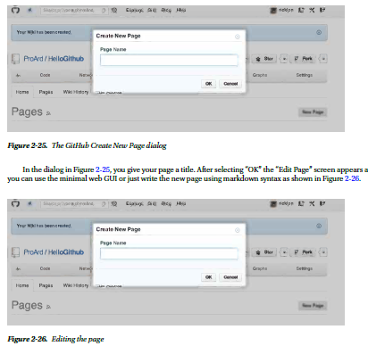
After entering the text in Figure 2-26, select the “save” option and the completed page appears. Figure 2-27 shows
the published page you just saved

Finally, you need to link the new page back to the home page by editing it and adding the line:
[Home](wiki/Home)
Anything between the brackets will be the hyperlink text. Then anything between the parentheses will be the
link. In our case, we link the “wiki” and the page called “home.” Anywhere this code appears will link back to the main
“Home” page.
Using Markdown
Markdown is an efficient syntax for quickly generating wiki pages. GitHub-flavored markdown is very code friendly and
easy to use. More details of GitHub markdown are found here: https://help.github.com/articles/github-flavoredmarkdown.
Also, the HelloGitHub project has an interactive version of this file here: https://github.com/ProArd/
HelloGithub/wiki/Markdown. The following are the basic code and page formatting options to get started quickly:
Code Blocks
We work with a lot of code in documentation, and showing examples quickly and easily is critical. To indicate a code
section, we use three back ticks “```” to start a code block and we use three more back ticks “```” to close a code block.
This makes it simple to add code into your documentation and examples. You can also specify the type of highlighting
for your project. In the case of Arduino projects, you would be using C++ or C as the formatting and coloring options.
You can choose not to show highlight with “no-highlght”.
Markdown:
```C++
/*
* Code goes here.
*/
void setup() {
}
void loop() {
}
```
Display:
/*
* Code goes here.
*/
void setup() {
}
void loop() {
}
Linking to files.
The label for the hyperlink is placed between square brackets “[ ]”, and then the link is placed between the parentheses
“( )”, as in the example. When linking external documents or images, the full link can go inside the parentheses. When
linking to pages or files in the wiki, the the entry needs to begin “(wiki/”, and everything after that is a page name or
filename completed by the last “)”
Markdown:
[Link to remote site](http://github.com/proard)
[Link to remote file]( https://github.com/ProArd/attinysecretknock/blob/master/ATtinySecretKnock/
ATtinySecretKnock.ino)
[Link to wiki files](wiki/TestLink)
Output:
Link to remote site
Link to remote file
Link to wiki files
The results are hyperlinks with the link to labels.
Headings
Heading values are determined by the number of hash “#” symbols. A level 1 header would be one “#”, level 2 “##”, and
level 3 “###”.
Markdown:
# H1
## H2
### H3
#### H4
Output:
H1
H2
H3
H4
Lists
Lists can be ordered or unordered. It is possible to mix and match ordered and unordered lists. These shortcuts
appear just like html ordered and unordered lists.
Ordered lists
Ordered lists just need to start with a number. GitHub wiki will substitute the correct sequence number.
Markdown:
10. item 1
9. item 2
Output:
1. item 1
2. item 2
Unordered lists
Unordered lists can use *, -, or, + as symbols. It doesn't matter which as long as there exists a space between the
symbol and the start of the list value.
Markdown:
* item a
+ item b
- item c
Output:
• item a
• item b
• item c
Linking to Images
Linking to images is just another version of linking. Except the brackets “[]” denote the alt text for the image. The
parentheses hold the link to the image. If the image is in your project you can hyperlink to the raw file. It is possible to
add the image to your project wiki by checking out the project's GitHub wiki, adding an image, committing, and then
pushing it back into your GitHub project wiki. The HelloGithub project wiki can be found here:
https://github.com/ProArd/HelloGithub/wiki/_access
Here’s the syntax of Markdown code to place an image, followed by a specific example:

Markdown:


Normal Text
For normal text you can type standard sentence structure. Paragraphs will automatically break at the new line. This
combination of links, code formatting, and basic information structuring can get you started documenting your
project. More importantly, effective documentation can help people understand why project is important, how they
can help support it, and when to join in with you to document it.
Contributing to Arduino Development
Now that you're comfortable with the concepts and tools of social coding, I'll present an example workflow that sets
up an Arduino social development environment, using the concepts and tools discussed in the preceding sections of
this chapter.
The proper way to contribute code and fixes to the Arduino project is to fork the repository to your own area
on GitHub. Then you can make changes to your repository and commit those changes to your repository. Next,
you create a pull request on GitHub for those changes to be merged into the main project. This pull request can be
reviewed, and then rejected or accepted into the project.
Forking Your Own Copy of Arduino
Here are the steps you would use to configure your own repository from Arduino’s official repository on GitHub.
Figure 2-28 shows Arduino GitHub project page.
1. Log into GitHub at http://github.com.
2. Go to the Arduino project:
http://github.com/arduino/Arduino.
3. Select Fork for the Arduino project on the GitHub interface. This places a copy of the
Arduino repository into your own GitHub area. Now that you have that in place, you need
to clone your copy of Arduino to your local machine. This process is called cloning your
fork of Arduino, and can be accomplished with the following command:
$ git clone git@github.com:username/Arduino.git
4. If you don’t need the entire project history, use this instead:
$ git clone git@github.com:arduino/Arduino.git --depth 1
5. Set the official Arduino repository as the upstream repository. The upstream repository is
needed so that you can pull down new code that other people add to the Arduino project.
Here are the commands to do so:
$ cd Arduino
$ git remote add upstream git@github.com:arduino/Arduino.git
6. Now that you have this in place, you can start editing the code. After a while, you'll want to
fetch and merge changes from Arduino every time new code is added. This is done with
the following commands:
$ git fetch upstream
$ git merge upstream/master

Once you have the your own fork, and have cloned it locally you will want to compile and run the Arduino IDE
from source code. Arduino has documented this process here: https://code.google.com/p/arduino/wiki/
BuildingArduino. Once you are able to run the software using “ant run” you can now make changes to the source
code. It is now possible to find issues in the Arduino project’s issue list and fix them. Using the social coding
techniques you will be able to make changes to the software, and submit your changes as pull requests back to the
Arduino project. It’s a big challenge to get this far with a large project, but it is really worthwhile to be able to make a
great project even better with the power of the open source community.
The combination of tools allows for complete issue tracking and code management.
How to build the Arduino IDE from source
Now that you have the source code, you will want to run the code to identify the changes and test that everything is
working. There is a straightforward process for doing this, but installing the toolkit is a little bit tricky. The process is
different for the Windows, Mac OS X, and Linux platforms.
For Windows:
1. Install Cygwin:
2. Install JDK
3. Install ANT
4. Configure ANT home directory
5. Install GIT (you may have already installed it)
6. Clone your fork of Arduino or Clone Arduino
7. Go to project directory
8. Go to build directory
9. Type “ant clean”
10. Type “ant run”
For Mac OS X:
1. Install ANT
2. Configure ANT home directory
3. Install GIT (you may have already installed it)
4. Clone your fork of Arduino or Clone Arduino
5. Go to project directory
6. Go to build directory
7. Type “ant clean”
8. Type “ant run”
For Linux:
1. Install JDK:
2. Install ANT
3. Configure ANT home directory
4. Install GIT (you may have already installed it)
5. Clone your fork of Arduino or Clone Arduino
6. Go to project directory
7. Go to build directory
8. Type “ant clean”
9. Type “ant run”
Any Java compilation errors will stop the run. Any updates to the core files must be tested by compiling and
uploading.
Community Resources
The Arduino community is a great source for both beginning and experienced developers. The community allows
for users to share their experiences and help one another learn new skills and troubleshoot difficult problems. The
following list provides some valuable resources offered by the Arduino community:
• The Arduino blog (http://arduino.cc/blog)
• The Twitter feed for the Arduino team (http://twitter.com/arduino)
• The Arduino forums (http://arduino.cc/forum/)
• The developer mailing list (https://groups.google.com/a/arduino.cc/
forum/?fromgroups#!forum/developers)
• The Arduino Playground (http://arduino.cc/playground/)
• The Arduino Style Guide for Coding (http://arduino.cc/en/Reference/StyleGuide)
• The Arduino Style Guide for Writing Libraries (http://arduino.cc/en/Reference/
APIStyleGuide)
Summary
Using the social-coding practices outlined in this chapter, you’ll be able to create projects that can transition
from personal projects, to group projects, to professional projects that use version control, issue tracking, and
documentation. By using these processes, you can also join other open source projects and contribute feedback,
documentation, issues, and code fixes. If you follow these procedures, your code and ideas can find there way into
Arduino projects as features, fixes, and new libraries.
The patterns outlined in this chapter will be used throughout the book and code examples. All the code examples
can be found at and forked from http://github.com/proard.
Chapter 3
openFrameworks and Arduino
openFrameworks is a set of C++ libraries that provides an easy method of coding audio, video, and graphical
components. openFrameworks provides mechanisms to easily connect serial devices and Arduinos to personal
computers, making openFrameworks an invaluable tool for Arduino development and a useful next topic for
discussion.
openFrameworks can be compared to interlocking plastic construction bricks in that using individual units does
not require knowing how to make them. The libraries of openFrameworks are a lot like boxes of construction bricks,
allowing creativity to flow without having to code from the ground up and always having a piece that will work. This is
done by utilizing C++ object-oriented programming methods, which add abstraction and reusability. The advantage
to openFrameworks in a development scene is that you can put together proofs of concept without having to do a
lot of low-level coding. Working in openFrameworks also provides working code that can be used as a blueprint to
migrate from when a final project goes into production and needs more optimizations.
Incorporating both openFrameworks and Arduino helps create a proof-of-concept environment for hardware
and software interaction, which uses a development approach that “work fosters ideas”; an exploratory development
style where ideas can be explored without waste. The key to this is reusability: not having to worry about permanently
using a resource and having plenty components to play with. The combination of openFrameworks and Arduino is
cross compatible on most systems.
The disadvantages to this setup are that it may not be production quality, optimized, reliable, or usable for the
masses; things that are arguably less important than sharing and exploration in idea generation. The disadvantages
are taken care of when moving away from the proof of concept to a prototype or putting the project into production.
For developers, showing an idea is more impressive when that idea is something that can be fully manipulated.
Physical models go a long way toward helping ideas to take life and can be easily created with clay, wood, 3D printing,
or various other means. Adding openFrameworks and Arduinos to a physical model can, for example, help you create
a new game controller design that can be used to play games.
Arduino and openFrameworks comprise a nice tool set to help breathe that extra life into an idea. With its simple
code structure, designers, artists, it gives developers the ability to add buttons to make LEDs blink, create controllers
to move virtual objects, and make systems that manipulate physical objects. Both Arduino and openFrameworks have
vast online communities and a plethora of other documentation, making the knowledge to work and develop with
these systems easily available. This chapter focuses on connecting the Arduino to computers via openFrameworks to
expand the functionality of the Arduino.
Getting Started
To get started, make sure that the openFrameworks and Arduino software are set up and working, and also make
sure there is a compatible Arduino board (e.g., an Uno, Leonardo or Nano) available. To download and install
openFrameworks, go to www.openframeworks.cc and follow the setup instructions for your system. openFrameworks
requires C++ and is built for integrated development environments (IDEs) such as Code::Blocks (www.codeblocks.org),
Visual C++ (www.microsoft.com/express), and Xcode (http://developer.apple.com/xcode/).
Chapter 3 ■ openFrameworks and Arduino
48
The first four examples in this chapter (Listings 3-1 to 3-4) show how to set up serial communications. All the
examples are written using Arduino 1.0.1 and openFrameworks version 0071 but have been tested with Arduino
1.5.1r2 and openFrameworks 0073.
Arduino Code
Listing 3-1 shows the code to set up the Arduino, connect to a push button on pin 8, and check if the button is pressed
or released and report the change in this state to a serial connection using a character. The code also checks for an
incoming character from the serial; a and s signify turning on and off an LED on pin 13, respectively. This passing of
characters is important when developing code for openFrameworks to control the Arduino, thus making the Arduino
a possible controller for a game, a sensor for a door, and so on.
Listing 3-1. Arduino Sketch That Sets Up the Arduino
int button = 8 , ledPin = 13; // pin assignments: button on pin 8,LED on pin 13
boolean oldState = 0 , newState = 0; // state change variables
void setup() {
pinMode(button, INPUT); ////////////////////////////
pinMode(ledPin,OUTPUT); // set pin I/O types
Serial.begin(9600); // starts serial at baud rate 9600
} // end setup()
void loop() {
newState = digitalRead(button); // save current button state
if(newState != oldState){ // test for change in button state
if (newState == true) // for button press, send the "h" to serial
Serial.print('h');
if (newState == false) // for button release, send the "l" to serial
Serial.print('l');
} // end if(state0 != state1)
oldState = newState; // save new state to old state for comparison
delay(40); // delay for bounce control
} // end void loop()
void serialEvent() { // called upon incoming serial
switch (Serial.read()){ // determine if serial is one of the required inputs
case 'a': digitalWrite(ledPin, HIGH);
break; // for input of "a", turn on LED
case 's': digitalWrite(ledPin, LOW);
break; // for input of "s", turn off LED
} // end switch (Serial.read())
} // end serialEvent()
■■Note T he serialEvent() function does not work with the Leonardo board. To convert for the Leonardo board change
void serialEvent() to if (Serial.available() > 0) and move the loop ending bracket to below the ex void
serialEvent() function.
Verifying the Code
Load Listing 3-1 and hook up the Arduino with a momentary push-button switch and a pull-down resistor hooked
to pin 8. The LED set up on pin 13 is optional because the Arduino has one on the board. With the board
set up as per Figure 3-1 and plugged in, start the serial monitor in the Arduino IDE and match the baud rate of 9600.
When the button is pressed, it causes an h or an l character to be displayed for a high or low state change. Sending the
Arduino an a or an s will turn on or off the LED.

Arduino Serial Functions
Listed following is a reference of Arduino serial functions and what they are used for. These functions reside in the
predefined Serial object. To call any of the serial functions, use Serial. before the name, like so:
Serial.begin(9600);
• void begin(speed): Opens and sets a serial port at a baud speed equal to an unsigned long.
Returns nothing.
• void end(): Closes the serial connection, releasing the TX and RX pins.
• int available(): Checks for data in the serial buffer and returns the number of bytes in the buffer.
• int read(): Returns the first incoming byte in the serial buffer as an int, and then removes
the byte. Successive reads will move through the buffer, much like dealing a deck of cards.
• int peek(): Reads the incoming serial buffer’s first byte, returns as an int, and leaves the data
in the buffer. This function is like peeking at the top card of a deck of cards.
• void flush(): Clears the serial buffer’s data. flush() will clear data after the buffer data is sent out.
• size_t print / println (value, format): Sends a human-readable translation of data.
Digits are sent as ASCII-equivalent strings, and characters are sent as bytes. This function can
have a format of DEC, HEX, BIN, or OCT. format can also be used to define the number of
bytes to send. println is the same as print, except it sends a new line to the end of the value.
Returns the number of bytes sent; reading is not required
• size_t write(value, size): Sends data in binary bytes instead of ASCII. write() can send
a single byte value, in which case size is not needed. A string and buffer are sent as a series of
bytes. size declares the buffer’s number of bytes to send. Returns the number of bytes sent.
• void serialEvent(){ }: Can be added to a sketch that is called any time there is incoming
serial activity.
openFrameworks Setup
With the Arduino code outputting and accepting input from the serial monitor, other programs can be developed
using C, C++, Java, or any other computer language from scratch to connect the Arduino to the computer. Coding
from scratch, however, can be a bit tedious for a proof-of-concept project. openFrameworks provides a nice prebuilt
interface for programming serial with C++ and also adds many other useful tidbits for audio and graphics. The next
set of examples will show how the openFrameworks libraries can be used to connect to the Arduino and the sketch
from Listing 3-1.
To verify that openFrameworks is working properly and the library is compiled, make a copy of the empty
example folder in the openFrameworks distribution; keep the folder in the same directory and rename it to ch3.
■■Note T he examples are located in the openFrameworks examples directory. An empty example to start with is
located in the apps/myApps subdirectory of the openFrameworks main directory.
Open the workspace for Code::Blocks or the VC++ project file in the renamed folder, and then compile. Two
things should compile: emptyexample and libopenFrameworks. After both parts are compiled successfully,
openFrameworks is ready for new code. Coding the examples in this chapter for openFrameworks applications is
done in the Code::Blocks project file or the Microsoft Visual Studio solution (not the one named libopenFrameworks,
but the one named after the project—e.g., emptyexample.workspace). The files for the examples in this chapter are
available for download from www.apress.com/9781430239390 and are contained in three files: main.cpp, testapp.cpp,
and testapp.h. These three files can replace the files with the same name that are in the renamed folder src
directory.
■■Caution M oving and compiling projects outside of the openFrameworks apps/examples directory may cause
dependencies issues. To solve this, point all the dependencies to the location of the openFrameworks main directory.
In 32-bit GNU/Linux, the workspace file for Code::Blocks may point to the 64-bit libraries. Solve this by opening the
workspace file in a generic text editor and change linux64 to linux.
Connecting to the Arduino from openFrameworks
Listings 3-2 through 3-4 make up the three files to create and run a basic openFrameworks program to connect to
an Arduino to send and receive data without having to use the serial monitor or console, while also providing extra
computing power by allowing the Arduino to connect to a C++ program.
Chapter 3 ■ openFrameworks and Arduino
51
Listing 3-2. main.cpp
#include "ofMain.h" // include files
#include "testApp.h" // declarations for the testapp class
#include "ofAppGlutWindow.h" // for using OpenGL and creating windows
int main() {
ofAppGlutWindow window; // sets up an OpenGL window object
ofSetupOpenGL(&window,200,100, OF_WINDOW); //sets window size in pixels
ofRunApp(new testApp()); // create testapp object & enter program loop
} // end int main()
openFrameworks code is set up to be event driven and window based, the same as other graphical-interface
programs. The main.cpp file contains the main() function, which is the entry point to the openFrameworks programs.
The main() function sets parameters for the window, including the window size and window mode. It is rare to make
many changes in main.cpp; most of the time the only thing that will change is the window size.
Listing 3-3. testapp.h
#include "ofMain.h"
class testApp : public ofBaseApp{
public:
void setup(); // for setting initial parameters
void update(); // code in this function is constantly run, events will interrupt
void draw(); // runs after update,this updates & creates the window objects
void mousePressed(int x, int y, int button); // on event function
bool SendSerialMessage; // signals that data needs to be sent
char ledcommand ; // hold what state the LED is in
char Returned; // hold returned char from Arduino
ofSerial serial; // this is the object to handle serial
};// end class testApp : public ofBaseApp
The testApp class inherits common functionality from the ofBaseApp class. This is where the function prototypes
are created. Variables that will be used in many functions can be declared here. There is a set of functions that are
called when events occur, such as mouse movement or using the keyboard. Note the line where you need to change
COM4 to match your Arduino setup.
Listing 3-4. testapp.cpp
#include "testApp.h"
void testApp::setup(){
ofSetVerticalSync(true); // helps to smooth out object drawing
ofBackground(255,255,255); // set background color to an RGB value
serial.setup("COM7", 9600); // change "COM7" to match where the Arduino is
ledcommand = 's'; // set initial state of the LED
serial.writeByte(ledcommand); // tell Arduino of the initial state
SendSerialMessage = false; // nothing to send yet
} // end void testApp::setup()
void testApp::update(){
if (SendSerialMessage) // is there serial information that needs to be sent
serial.writeByte(ledcommand); // tell the Arduino to change LED state
if (serial.available()) // check to see if there is incoming data
Returned = serial.readByte(); // save the incoming data
SendSerialMessage = false; // reset the need to send data to the Arduino
}//end testApp::update
void testApp::draw(){ // defines placement and draws objects in the window
ofFill(); // fills geometry with a solid color
if (Returned == 'h') // is the button on the Arduino being pressed
ofSetColor(0,0,255); // set the first circle color to full blue
else // the button is not pressed or the state is not known
ofSetColor(0,0,127); // set the first circle color to 1/2 blue
ofCircle(50,50, 50); // draw the first circle at last set color
if (ledcommand == 'a') // should the LED be on
ofSetColor(0,255,0); // set color to full green for the second circle
else // LED should be off or not known
ofSetColor(0,127,0); // set color to 1/2 green for the second circle
ofCircle(150,50, 50); // draw the second circle at last set color
} //end void testApp::draw()
void testApp::mousePressed(int x, int y, int button){
SendSerialMessage = true; // inform update function that there is data to send
if(ledcommand == 'a') // if the LED is ON
ledcommand = 's'; // change LED to be OFF
else // if the LED is OFF
ledcommand = 'a'; // change LED to be ON
} //end testApp::mousePressed
Verifying the Code
Make sure that the Arduino that was set up in Listing 3-1 is plugged into the computer and take note of the port that it
is plugged into.
• COM* is for Windows
• /dev/tty* is used for Linux/Unix and Mac OS X
Change the serial.setup(COM4,9600) line in Listing 3-4 to match the Arduino’s connecting point. Once the test
app is set to know where the Arduino is, compile the examples. Running the program will open a window frame that
looks like Figure 3-2, with the first circle representing the push button and the second circle showing the state of the
LED. To change the LED state, click in the window with the mouse.
Chapter 3 ■ openFrameworks and Arduino
53
openFrameworks Serial Functions
The following reference list is for the openFrameworks serial functions. Most of the functions work just like the
Arduino’s counterpart functions. The serial object must be declared before using and calling the openFrameworks
serial functions. The serial object comes from the ofSerial class; just as a variable is declared, a serial object is
created by using the following:
ofSerial serial;
To use any of the functions, use the name declared for the object—for example, serial.setup();. Here are the
functions:
• void enumerateDevices(): Lists the available serial devices.
• void close(): Closes the serial connection.
• bool setup(int, int): Connects to the device number corresponding to the list outputted by
enumerateDevices() at the desired baud speed.
• bool setup(): Opens a serial connection on the first available device at baud 9600 and returns
a fail or succeed.
• bool setup(string, int): Uses a string to declare what serial device to connect to. The
second parameter sets the baud speed and returns a fail or succeed.
• int readBytes(unsigned char, int): Takes a pointer to an array of characters, attempts to
retrieve the number of bytes equal to the second parameter, and returns the number of actual
bytes read (compare to the requested amount of bytes to error-check).
• int readByte(): Returns a single byte from the connected device.
• int writeBytes(unsigned char, int): Takes a character array or string and an amount of
bytes to write, and returns the amount written for error checking.
• bool writeByte(unsigned char): Sends a single byte to the connected device and returns a
fail or succeed.
• void flush(bool, bool): Clears one or both of the serial buffers (one buffer for send, one
buffer for receive).
• int available(): Returns the number of available bytes in the receive buffer.
Coding Once Using Firmata and ofArduino
In keeping with the spirit of “work fosters ideas,” working with two different pieces of code (one on the Arduino
and one using openFrameworks) is a bit inefficient for exploring ideas, especially when changing things frequently.
Luckily, there are items included with the Arduino IDE and openFrameworks (a program for the Arduino and a
built-in class for openFrameworks) that make it possible to write single programs that take care of having to separately
code the Arduino.
• Firmata is a communication protocol for the Arduino that allows for on-the-fly configurations
without having to restart or reprogram the Arduino. Standard Firmata is included with the
Arduino IDE.
• openFrameworks complements Firmata by including a class called ofArduino, which handles
both communication and configuration of the Arduino.
Setting Up Firmata
Set up the Arduino board with the components connected as in the schematic in Figure 3-3, and then upload the Standard
Firmata sketch. The sketch is located in the Arduino IDE under File ➤ Examples ➤ Firmata ➤ StandardFirmata.

To verify that Firmata is working on the Arduino, download and run the test app from www.firmata.org/. Select
the port to connect to from the drop-down menu, and the app will show all the pins, which have drop-down boxes for
pin configuration and buttons for output values, as shown in Figure 3-4.
■■Note T he Leonardo need the Firmata library updated. Instructions and updated library available at
www.github.com/soundanalogous/Breakout/wiki/Updating-Firmata-in-Arduino

The Firmata test app is especially usefully for testing out component setups that use multiple pins, such as a
three- to eight-line MUXs, seven-segment displays , keypads, and servomotors.
Controlling the Arduino with openFrameworks
The code in the next example uses the same main.cpp as Listing 3-2. The header file testapp.h in Listing 3-5 still
declares the class function prototypes setup(), update(), draw(), and mousePressed(). The two new function
prototypes are set up to mimic the Arduino’s coding structure. The function arduinoSetup() is for initializing pin
configurations, and the function arduinoLoop() is the equivalent to loop in Arduino sketches.
Listing 3-5. testapp.h for the Standard Firmata Sketch Communication
#include "ofMain.h"
#include "ofEvents.h"
Chapter 3 ■ openFrameworks and Arduino
56
class testApp : public ofBaseApp {
public:
void setup();
void update();
void draw();
void mousePressed(int x, int y, int button);
void arduinoSetup(const int & version); // Arduino equivalent setup function
void arduinoLoop(); // Arduino-equivalent loop function
bool ledcommand;
bool pin13; // pin13 data container
bool pin8; // pin8 data container
float analogPin0; // pin8 data container
bool isArduinoSet; // flag to know when Arduino is connected and configured
ofArduino arduino; // the Arduino object
}; // end class testApp : public ofBaseApp
In testapp.cpp of Listing 3-6, the functions arduinoSetup() and arduinoLoop() perform the same
functions of an Arduino sketch with openFrameworks on top of the Arduino-style functions. Firmata and the
openFrameworks ofArduino class make the serial communication less apparent. By carefully mimicking the same
structure as an Arduino sketch, the conversion to an actual Arduino sketch is made simpler if the conversion
becomes necessary, as when moving to a more professional setup. Keep in mind it is possible to develop code in
openFrameworks that may require more space and computing power than might be available on the Arduino. This
is especially important to remember when using Firmata as a tool in making proofs of concept to eventually be
used solely on the Arduino.
■■Note Firmata is capable of using I2C and other communication functionality; however, openFrameworks does not
currently support I2C functionality (as of version 0071).
Example 3-6. testapp.cpp for Standard Firmata Communication
#include "testApp.h"
void testApp::setup() {
arduino.connect("COM7"); // remember! change this to the proper port
ofAddListener(arduino.EInitialized, this, &testApp::arduinoSetup);
/*the ofAddListener waits for the Arduino to perform a handshake telling the program that it is
ready to be configured and set up. This will call arduinoSetup*/
isArduinoSet = false; // this flag is set false until the Arduino is set up
} // end void testApp::setup()
void testApp::update() {
testApp::arduinoLoop();// perform the Arduino-style code
} // end void testApp::update()
void testApp::draw() { // objects are drawn to the screen in the order called
if (isArduinoSet){ // do not run this code until Arduino is operating
ofFill();
if(pin8 == ARD_HIGH)
ofSetColor(0,0,255);// if button on pin8 pressed, brighten the circle
else
ofSetColor(0,0,127);// blue is dim if button is released
Chapter 3 ■ openFrameworks and Arduino
57
ofCircle(50,50,50); // draw circle at (x,y,radius) in pixels for button
if(pin13 == ARD_HIGH)
ofSetColor(0,255,0); // when LED is on, draw full green
else
ofSetColor(0,127,0);// green is dimmed when LED is off
ofCircle(150,50, 50); // draw circle at (x,y,radius) in pixels for LED
ofSetColor(255,0,0); // set color for analog potentiometer
// draw rectangle with corners at (x1,y1,x2,y2)
ofRect(0, 45 ,(analogPin0*200) , 10); // rectangle is dynamic on the x-axis
// analogPin0 is a percentage multiplied by window width
} // end if (isArduinoSet)
}// end void testApp::draw()
void testApp::mousePressed(int x, int y, int button) {
if(ledcommand == true) // if LED is ON
ledcommand = false ; // flag the LED to turn OFF
else // the LED is OFF
ledcommand = true; // flag the LED to turn ON
}// end testApp::mousePressed
void testApp::arduinoSetup(const int & version) {
ofRemoveListener(arduino.EInitialized, this, &testApp::arduinoSetup);
// there is no need to continue to listen for the Arduino, so clear memory
arduino.sendAnalogPinReporting(0, ARD_ANALOG);// turn on analog pin0
arduino.sendDigitalPinMode(8, ARD_INPUT);// set digital pin8 as input
arduino.sendDigitalPinMode(13, ARD_OUTPUT);// set digital pin13 as output
isArduinoSet = true;// inform the rest of the program that Arduino is ready
}//end void testApp::arduinoSetup(
void testApp::arduinoLoop() {
// do not run this code until Arduino is operating
if (isArduinoSet){
pin8 = arduino.getDigital(8);// digital read pin8
pin13 = arduino.getDigital(13);// digital read pin13 verifying state
analogPin0 = arduino.getAnalog(0)/1023.0; // analog read A0
arduino.sendDigital(13, ledcommand);// digital write new state
}// end if (isArduinoSet)
arduino.update();// get any changes that the Arduino might have
}// end void testApp::arduinoLoop()
Verifying the Code
When done looking over and compiling the code, plug in the Arduino with the components set up in as Figure 3-3 and
the standard Firmata sketch uploaded. When running, the program will open a window with the same size as the prior
example. The program will also have the same two circles representing the button and LED, respectively performing
the same functions. A red bar is added to the program that will go from side to side, representing the full sweep of the
potentiometer.
■■Note T he Arduino may be required to reset, via the reset button, before the listener initializes and recognizes the
Arduino. The listener is built into openFrameworks to listen for an Arduino on the connection.
Chapter 3 ■ openFrameworks and Arduino
58
Key Constants Used by ofArduino
ofArduino defines some useful constants for more readable code. The following list is a reference of names and values
of the constants. The first part of the constants, ARD, is short for Arduino, and is a reminder that this is dealing with the
hardware. The second part is the type—for example, the pin modes or state declarations.
• Pin modes:
• ARD_INPUT = 0x00
• ARD_OUTPUT = 0x01
• ARD_ANALOG = 0x02
• ARD_PWM = 0x03
• ARD_SERVO = 0x04
• Pin states:
• ARD_HIGH or ARD_ON = 1
• ARD_LOW or ARD_OFF = 0
ofArduino Reference of Class Functions
The following list is a reference for the class functions that make up the ofArduino class. The functions that are
included in the ofArduino class are used to control and connect to Arduinos that have the standard Firmata sketch
loaded. Most of the functions are a direct counterpart of the functions used in the Arduino IDE and work the same
way; for example, sendDigital() is the same as digitalWrite(). The functions require an ofArduino object declared
before they can be used. You can connect multiple Arduinos to the same computer by declaring separate objects for
each Arduino.
• bool Connect(port, speed): Opens an Arduino connection on a serial port and takes a
string for the device connection, such as /dev/ttyUSB0, COM4 or /dev/tty.usbserial-A4001JEC.
The second parameter is for nondefault baud speeds and can be omitted in
standard configurations.
• void disconnect(): Releases the Arduino connection.
• bool isInitialized(): Returns true if a successful connection has been established and the
Arduino has reported that firmware from the Firmata sketch has been uploaded.
• void update(): Used to update the current state of the Arduino’s incoming information; this
should be called regularly.
• void sendDigitalPinMode(pin, mode): Sets the pin mode of a digital pin (one of pins 2
through 13) and sets the pin as one of the digital modes of ARD_INPUT, ARD_OUTPUT, ARD_PWM, or
ARD_SERVO. If the pin is an input, the reporting will be turned on.
• void sendAnalogPinReporting(pin, mode): For analog pins 0 through 5, turns the reporting
to ARD_ON or ARD_OFF. Analog pins can be used as digital pins 16 through 21 or as PWM pins.
The whole group is either analog or digital.
• void sendDigital(pin, state): Sets the state of the specified digital pin to either ARD_LOW or
ARD_HIGH.
Chapter 3 ■ openFrameworks and Arduino
59
• void sendPwm(pin, value): Sets the PWM value for pins set to ADR_PWM (chosen from pins 3,
5, 6, 9, 10, and 11); the value is between ON (255) and OFF (0).
• void sendServo(pin, sweep): Uses pin 9 or 10 and sends servo signals between 0 and
sweep-angle default 180.
• void sendServoAttach(pin, min, max, sweep): Defines the following servo parameters:
• The pin
• Minimum pulse width (defaults to 544)
• Maximum pulse width (defaults to 2400)
• Angle of sweep (defaults to 180)
• int getDigital(pin): Used on pins 2 through 13:
• For pins set as ARD_INPUT returns the last state the pin reported
• For pins set as ARD_OUTPUT returns the last value sent to the pin
• int getPwm(pin): For pins set as ARD_PWM, returns the last set PWM value for the pin
requested (usable pins are 3, 5, 6, 9, 10 and 11, or pins 16 through 21 if analog pins 0 through 5
are set as digital pins).
• int getServo(pin): Returns the last value the servo was set to.
• int getAnalog(pin): Used for analog pins 0 through 5 and returns a value between
0 and1023.
• string getString(): Returns the last string received.
• int getDigitalPinMode(pin): Returns ARD_INPUT, ARD_OUTPUT, ARD_PWM, ARD_SERVO, or
ARD_ANALOG.
• int getAnalogPinReporting(pin). For analog pins 0 through 5, returns ARD_ON or ARD_OFF.
Expanding on the Idea
We now have openFrameworks controlling the Arduino, which is running the standard Firmata sketch. The
next example illustrates the increase of efficiency that can be gained in development by having Arduino and
openFrameworks integrated.
1. Start the next example by attaching a servo to pin 10 and another LED to pin 3, in addition
to the other components from the last example. Use Figure 3-5 for reference.
2. After the two new components are in place, start the Firmata test app to check that all the
components are working.
3. Set the pins to the following configuration:
• pin3 = PWM
• pin8 = input
• pin10 = servo
• pin13 = output
• Analog pin 0

For the hardware, the potentiometer is going to control the servo, while the brightness of the LED on pin 3 will
represent the position of the servo. When the button is pressed, the LED on pin 13 will turn on; at the same time, the
servo and the other LED will pause and stop accepting new values from the potentiometer until the button is released.
Changing Code
While openFrameworks is controlling the Arduino, it will simultaneously be displaying a representation of what the
hardware is doing. The program will have a window the same size as the two prior examples, with shapes representing
the button, the LED, and the potentiometer’s position. The only change to the graphics is that we will dynamically
change the color of the bar to represent the new brightness value for the LED, with the color fading from black to full
red with the servo and potentiometer’s full swing.
Open the project from Listings 3-5 and 3-6. The same main.cpp will be used without alteration. Within
testapp.cpp, the entire mousePressed() function can be removed or commented out, along with its prototype in
testapp.h. You can omit the following line from the arduinoLoop() function:
arduino.sendDigital(13, ledcommand);
The last thing to comment out is the variable declaration bool ledcommand; from testapp.h. With the code that
is no longer needed out of the way, change the line ofSetColor(255,0,0);, located in the draw() function, to
ofSetColor((analogPin0*255),0,0);
This change takes advantage of the analog percent value to evenly change the color in proportion
to the bar.
Add the following code to the arduinoSetup() function below the code line
arduino.sendDigitalPinMode(13, ARD_OUTPUT); defining the new componets. Note that the text following the
comment delimiters (//) is optional.
arduino.sendDigitalPinMode(3, ARD_PWM); // set pin 3 for PWM
arduino.sendDigitalPinMode(10, ARD_SERVO);// set pin 10 to accept a servo
arduino.sendServoAttach(10);// define servo information as default
isArduinoSet = true;
Listing 3-7 shows the next portion of code to add, which is the last for this example. The code handles the button
pause, the servo, and the PWM LED, and gets inserted into the arduinoLoop() function before the ending bracket of
the if (isArduinoSet) statement and after analogPin0 = arduino.getAnalog(0)/1023.0;.
Listing 3-7. The End of “Expanding on the Idea” Example
if (pin8 == ARD_HIGH){ // check if button is being pressed
pin13 = true; // flag the draw function to change
arduino.sendDigital(13, ARD_HIGH);// turn on LED
} // end if pin8 == ARD_HIGH)
else {
arduino.sendDigital(13, ARD_LOW);
arduino.sendPwm(3,analogPin0*255);
arduino.sendServo(10, analogPin0*180);
} // end else
Verifying the Code
With all the code changed and compiled, start the program with the Arduino plugged in. The program should look
like Figure 3-6. When the screen is fully drawn, the pause button will have to be pressed to get the servo and the LED to activate.

The changes that were made make the Arduino act differently without your having to upload a new sketch.
Note that the changes now allow the potentiometer to control the sweep of the servo and the brightness of the LED
when the potentiometer is swept from maximum to minimum. Also take note of the behavior when the pause is held
while the potentiometer is being moved.
Chapter 3 ■ openFrameworks and Arduino
62
More Ideas to Work With
openFrameworks has a lot more functionality than described in this chapter. openFrameworks can manipulate sound
images or even 3D objects, and the connection to serial devices or Arduinos allows controllers to be built that can
control the computer. You can create programs to control the Arduino as well. With all the possible projects that you
can create using Arduinos, the extra features that openFrameworks provides may make it hard to decide where to go
and what to do. Try out some of the ideas listed below; they came up during a few brainstorming sessions. These ideas
should help further your exploration of openFrameworks while providing more experience with the platform.
Use a keypad t • o select a song from a playlist (i.e., make a jukebox).
• Make a small game using an old hard drive motor for the input controls.
• Create a logging system that records data to a database such as MySQL using Arduino and
openFrameworks.
• Build a dynamic scrolling LED marquee that also displays the characters being typed on the
computer screen.
• Create an RGB LED array to build a mood light that changes in response to audio or visual cues.
Summary
This chapter discussed the fundamental steps to integrate openFrameworks with Arduino. As a development tool,
openFrameworks may provide the catalyst that can take a good idea to the next step. Its versatility is only increased by
providing two great ways to develop: using serial or Firmata. With time and use, most developers will find a preference
for one method over the other.
openFrameworks has a lot more functionality than can be covered here, but this chapter should provide you
the knowledge and confidence to delve deeper into openFrameworks. Also check out other resources available; the
forums at www.arduino.cc/ and www.openframeworks.cc/ are great places to find more information. The examples
included with openFrameworks can also provide excellent insight.
63
Chapter 4
Android ADK
Since the introduction of the Android operating system in 2007, Android has become one of the more popular
embedded Linux distributions available to consumers and hobbyist for development purposes. Google provides a vast
knowledge base to help with getting started in developing Android-specific applications; the Google documentation,
reference material, and SDK are available at http://developer.android.com.
The popularity of Android development for the hobbyist can be attributed to the ease and cost of the available
information. The draw for vendors to use Android as an operating system for many types of consumer electronics is that
Android provides a great starting point by having much of the development for an operating system completed, and by
providing the capacity for many different hardware configurations. As an operating system, Android provides a framework
for vendors to add their own unique functionality, while having a support structure and standards of compatibility for
third-party content developers. The market environment for Android mimics that of Linux—each system has variations
within its individual distributions. The differences between Android versions and the modifications by vendors have led
to a fragmentation in support for development. This became more apparent when Google announced the Accessory
Development Kit (ADK) in 2011.
The ADK was announced to provide a toolkit to developers so that third-party devices could be made to expand
the hardware functionality of systems running Android. The ADK was first released for version 3.1 and then ported
back to version 2.3.4. The fragmentation of Android devices has made it difficult to develop commercial devices that
could be supported on a majority of systems running Android. The amount of off-the-shelf device support that can
support the ADK protocols could change as more devices adopt the Ice Cream Sandwich version of Android. The ADK
is comprised of two parts: a protocol for the device and hardware for the actual accessory.
When Google released the ADK software and libraries for the operating system, it also released a hardware kit
that resembles an Arduino Mega with a shield attachment, and since then, many open source hardware developers
have made boards compatible with the original ADK device. Seeed Studio and Arduino both make an ADK board
that uses the ATMega 2560 chip. Both boards work the same and can be programmed in the Arduino development
environment. SparkFun Electronics makes an ADK-compatible board named IOIO (pronounced Yo-Yo), but is based
on a PIC microcontroller and has a different programming environment.
At the heart of ADK methodology having a device that can act as a USB host give the impression that the Android
device is plugged into a computer to initiate communications. On the Arduino Mega ADK board, this is done by adding
an SPI-based USB host processor. The chip used in creating the host connection uses the SPI bus for data transmission
and is connected to the appropriate MOSI (master out slave in), MISO (master in slave out), SS (slave select), and
SCLK (serial clock) pins. The USB functionality also uses pin 7, making it unavailable for other uses. Arduino shields
are available to add the ADK functionality to other Arduino boards, such as the UNO and the basic Mega. Theses ADK
shields are created by third-party vendors, including SparkFun for the USB host (www.sparkfun.com/products/9947).
A variety of different host shields are also available from Circuits@Home (www.circuitsathome.com).
Devices that use the USB host chip are not limited to working with Android; they are also capable of working
with other client devices, such as USB keyboards. But the focus in this chapter is Android-specific functionality with
the Arduino Mega ADK. Before the ADK was available, hobbyists and makers were using a method that involved the
Android Debugging Bridge (ADB) to add the functionality that is available with the ADK. The ADK can be used to add
controls for robotics, read from nonstandard sensors, and interface with machines such as the MakerBot.
Chapter 4 ■ Android ADK
64
Android Devices
Before getting a board that is capable of USB hosting, you must locate a suitable Android target. As mentioned before,
not all Android devices are currently capable of handling the ADK protocol. Devices that were made before the release
of the ADK are the ones most likely not able to support ADK protocol without modification. Devices that use versions
of Android as old as or older than 2.3.3 are not capable of handling the ADK methods at all. The older devices are still
capable of using the ADB to create data connections.
What to Check For
For a device running Android to be nativity capable of using the ADK, the version must be 2.3.4 or later, but this not
conclusive. The conclusive check is in the Google Play app market: search for “ADK demo kit.” If it’s not available, the
device does not have the required libraries installed. It has been found that some devices are capable of installing the
demo kit, but lack an option that needs to be compiled into the operating systems kernel. This will show up when
the demo kit is installed and run. The ADK hardware does not have to be connected; if the demo kit app shows a
screen that asks for an ADK board to be connected the device is ready for ADK development.
Known Working Devices
Following is a list of Android devices that have been found to nativity work with ADK. (There are possibly more, with
new Android devices coming out almost daily.) The devices that have native support are prime targets for commercial
applications for developing accessories.
• Acer Iconia A100: This is a 7-inch tablet running Android version 3.2, running a dual-core
1 GHz Cortex-A9 with 1 GB of RAM.
• Acer Iconia A500: This is a 10.1-inch tablet with the same processor and RAM as the Iconia
A100, running Android version 3.2. Both of the Acer tablets are planned to be upgraded to Ice
Cream Sandwich at some point.
• ASUS Eee Pad Transformer TF101: This is 10.1-inch tablet with the same processor and RAM
as the Acer tablets; it runs Android version 3.2 and is upgradable to Ice Cream Sandwich.
• Google Nexus S: This is a phone made by Samsung for Google. This device runs a single-core
1 GHz Arm Cortex-A8 with 512 MB of RAM, running Android version 2.3 and upgradable to Ice
Cream Sandwich. This device is a Google development phone providing great support for new
APIs and developments.
• Google Galaxy Nexus: This is also a Google development phone made by Samsung. It uses a
dual-core 1 GHz Cortex-A9 with 1 GB of RAM and the Ice Cream Sandwich version of Android.
• LG Optimus Pad: This is an 8.9-inch tablet with a dual-core 1 GHz Cortex-A9 with 1 GB of RAM
running Android version 3.0.
• Motorola Xoom: This is a 10.1-inch tablet with a dual-core 1 GHz NVIDIA Tegra 2 with 1 GB of
RAM running Android version 3.0.
• Samsung Galaxy Tab 10.1: This is a 10.1-inch tablet with a dual-core 1 GHz NVIDIA Tegra 2
with 1 GB of RAM running Android version 3.1.
• Samsung Galaxy S: This is a phone with a single-core 1 GHz Arm Cortex-A8 with 512 MB of
RAM. This device can be factory-upgraded to Android 2.3 to work with the ADK.
• Samsung Galaxy Ace: This is a phone with an 800 MHz ARM 11 and 278 MB of RAM running
Android version 2.3.
Chapter 4 ■ Android ADK
65
Modding
The devices branded by Google are the better choice for heavy development. There are many devices that can be
made to work with the ADK, but may require modding, also known as rooting. Modding is a great way to achieve
extra functionality in an Android device. Modding is not without risks—for example, so-called bricking, voiding of
warranties, and the possibility of devices becoming unstable are the biggest problems.
If you decide to modify a device, do a sufficient amount of research and weigh the risks and cost before
proceeding. If you’re unsure about mods, either don’t do them or consult someone who has.
This chapter was developed with a Barnes and Noble NOOK Color running both CyanogenMod 7 (Android 2.3)
and CyanogenMod 9 (Android 4.0), dual-boot from the SD card. CyanogenMod is an aftermarket Android distribution
providing custom ROM for a variety of devices. You can find more information about it at the CyanogenMod web
site (www.cyanogenmod.com). CyanogenMod is developed by the community and has a lot of support, and is one of
the more popular aftermarket Android distributions. You can find great resources for modding and development of
Android systems at the XDA Developers forums (www.xda-developers.com).
I chose the NOOK Color as a development platform because of the cost, ease of modification, and decent
hardware specifications. CyanogenMod 7 for this device had to have a custom kernel compiled with the configure
flag CONFIG_USB_ANDROID_ACCESSORY set during the compile, and the usb.jar libraries added to the system.
CyanogenMod 9 for the NOOK Color can be installed on an 8 GB microSD card and booted—just like having multiple
bootable devices on a normal PC. You don’t need a NOOK Color for the examples in this chapter, although you will
need an Android device capable of using the ADK protocols.
Arduino IDE Setup
This chapter will provide an introduction to building a classic Hello World hardware example with an Android twist.
An Android device and an Arduino Mega ADK are needed for the rest of this chapter. Before any programming can
be done, the Android and Arduino environments need to be set up. The Arduino 1.0 IDE (or later) should already be
available, but a library is needed to work with the ADK protocol. The appropriate library is available from the Arduino
labs web site (http://labs.arduino.cc/uploads/ADK/GettingStarted/ArduinoADK-beta-001.zip).
Contained in the ZIP file are files for Processing and Arduino; you can ignore the Processing folder. In the
Arduino folder are two versions of the library. Extract the folder named UsbHost and the files located in the libraries
folder to the libraries folder for the Arduino IDE. Start or restart the Arduino IDE, finishing the installation of the
new library. Under File ➤ Examples ➤ UsbHost, examples should now be available. Open the first example and verify
that it can compile. Once finished, the Arduino IDE will be ready to program ADK applications.
You need to set up a development environment to write the Android code and make the installation packages.
Both Processing (http://processing.org) and Eclipse (http://eclipse.org) can create Android applications.
Programming in Processing is similar to programming Arduino code, but lacks some finesse and control. This chapter
focuses on the Eclipse IDE, which provides greater functionality but is a bit cumbersome. When using Eclipse for
Android development, you need to understand two different styles of code: the main Java-related portion and XML.
The Java-styled code is the grunt of any Android application and is the main programming language; XML is the
fluff that defines the layout, objects, and text that gets displayed. I’ll describe the programming methodologies for
application development a bit later in the chapter. If this is your first introduction to Android development, check out
Wallace Jackson’s Android Apps for Absolute Beginners (Apress, 2011).
Installing the Eclipse IDE is fairly straightforward. For best results, follow the instructions on the Android
Developers web site for your specific system (http://developer.android.com/sdk/installing.html). The
complicated part of the setup is making sure that the ADB functions properly; this may actuality require that you have
root access and that you turn on USB debugging in the device settings. To check if the ADB is working, in a command
prompt change to the platform-tools directory and run the command adb, and the command’s help should be
printed to the screen. If the command does not run from any other directory, check to see if the SDK’s installation
directory has been added to the environment variables.
Chapter 4 ■ Android ADK
66
Once the help is displayed plug the intended device for development into the computer, and run the command
adb devices to print a list of connected devices. If no device shows up, USB debugging might be turned off or root
accesses might be needed. The ADB is not necessary for loading applications on the device, but it is helpful to be able
to have the application automatically uploaded to the device from Eclipse when in development stages. If the ADB is
not available, the application’s APK file has to be manually installed on the system. For each change, a file manager
will have to be installed from the market, and the system has to allow for untrusted sources. You can set this in the
Manage Applications section in the systems settings. Eclipse has the ability to run emulators and use actual hardware
for debugging. It is helpful if the ADB is available to run an application called ADB Wireless, available from the apps
market. Note that this app requires root access. Running the ADB over a wireless network allows for the Arduino Mega
ADK to be constantly attached to the Android device and the computer during developments.
Android Application Creation
After the Eclipse IDE is set up, you’ll create a new Android project from the New Project wizard in Eclipse.
1. Choose File ➤ New ➤ Project, and then select Android Application Project in the Android
folder within the wizard selector, as shown in Figure 4-1.
Figure 4-1. Eclipse’s New Project dialog

3. Name the project CH4Examples.
4. Name the package CH4.example.proarduino. The package name is a triplet descriptor that
defines a base Java package that will be the program’s entry point. The application name,
project name, and package name can be set to anything for later projects and should be
set in the wizard when creating projects; note that once you’ve created these names for a
project, it is difficult to change them later on.
5. Next, you’ll set which API level to use. Select Google APIs for the 2.3.3 platform, API
version 10. The API sets the minimum version of Android that the application will work
on, API version 10 will work on future Android releases. Do not use Android X.X.X, where
X.X.X is the target version of Android, when developing ADK applications. Only the Google
APIs have the required support for the ADK.
6. You can also choose to create a custom logo for the application. For now, though, deselect
the “Create custom launcher icon” option. If the option is selected, you will be given an
additional set of prompts for setting the application logo.
7. Finally, leave the “Mark this project as a library” and “Create Project in Workspace”
options at their defaults, and then click Next.

Finally, you’ll set some of the names for some of the project’s internal files (see Figure 4-4).
Make sure that the names in the Activity Name and Title fields match those of the project’s
name, followed by Activity (e.g., CH4ExamplesActivity). For this exercise, change the
layout name to main. The layout name describes the first user interface that the program
will use by default. You can leave Navigation Type at the default of “None,” since this is
going to be a stand-alone application and does not require a parent program. For more
advanced applications, you can change this to accommodate different user interactions,
such as tabbed navigation.

When you click Finish, the wizard creates an autogenerated Hello World project and a *.apk file; these form the
framework for the rest of the examples in this chapter. If this is the first time an Android application is being set up,
there may be a need for the wizard to automatically download some extra software components.
If the ADB is set up and the device is available, you can load the basic app and start it on an Android device by
clicking on the Play button on the toolbar, selecting Run from the Run menu, or pressing Ctrl+F11. When the project is
initiated for the first time, Eclipse will ask how to run the application. Make sure to select “Android application” from
the options. After you have selected the Run As options, you need to select the device to run; if the ADB is working
and the device is connected an option will be shown to choose a running Android device. You can create an Android
Virtual Device (AVD) to test running an application if a physical device is not plugged in or one is simply not available.
Note that the AVD is not capable of testing ADK functionality, because of a USB host conflict.
The next section focuses on the Arduino and preparing to communicate with the ADK before building the actual
Android app.
■■Note I f you’re not running the ADB, you can copy the .apk file to an Android device from the workspace project
name/bin folder and install it by running .apk from the Android device.
The Arduino Sketch
Working with the ADK with the Arduino is similar to working with software serial, in that a header needs to be included,
an object declared, and that object started. The library that was added to the Arduino’s IDE provides a clean method
of declaring and initializing the host connection when compared to other libraries that are available, and is based
on the Circuits@Home libraries. The header that needs to be included is AndroidAccessory.h. The object is of type
AndroidAccessory and can be named anything; it has some information that is declared upon object creation. The data
that is declared when the AndroidAccessory object is created is for identification to any Android device that the board is
connected to, thus registering the Arduino to a particular application. The data is enclosed in parentheses and separated
by commas after the object’s name. The declared data is ordered and defined as manufacturer, model, description,
version, Uniform Resource Identifier (URI), and serial. The data is represented as a character string and can be any
reasonable number of printable characters. It’s always available to the connected Android device. The manufacturer,
model, and version are used to identify the accessory to a program on the Android device. The rest of declaration
information can be used for tracking and debugging reports in applications for widespread or commercial use.
The accessory is started the same way as software serial: by calling name.begin in the setup function of the
Arduino sketch. The object’s public functions—available, write, peek, and flush—perform the same work as
their serial or software-serial counterparts, along with print and println. There are two other functions to note
when working with the AndroidAccessory library. One is isConnected, which returns a Boolean for the status of
the connection between Arduino and Android. The last added function is refresh; it’s used to reset and reinitialize
the connection between the two devices after the devices have been reconnected. If the Arduino code checks for a
connection from the isConnected function, it will also call refresh to try to reestablish the connection every time
isConnected called. The use of refresh or an isConnected check in the Arduino code’s main loop creates the ability
to connect devices without having to power-cycle or rest the Arduino.
The first example sets up an LED to change state on the Arduino when a virtual button on the Android device
is pressed. The Arduino is set up as per Figure 4-5, with an optional LED connected to Arduino pin 13. The code
accomplishes the state change by receiving a 1 to turn on the LED and any other byte value from the Android device to
turn it off. The code also implements the refresh function to allow for reconnecting the two devices without resetting the Arduino.
